
Parametric Stairs in Blender
Fancy knowing how to create stairs in Blender with modifiers? Making a completely parametric stair is both possible and fairly easy, as long as we know a little bit about modifiers and vertex groups. Once the setup for the stairs has been made, it is easily modifiable. We can change the number of steps, the top and bottom side reaches, fillets angles, and more.
Blender has the excellent ability to be used as a tool for computational design due to the inherent parametric nature the software exhibits with modifiers. Let’s test what’s possible by creating parametric residential stairs that are completely adjustable.
Video Tutorial
Written Guide
To complement and to serve as a reference for the video tutorial above (or if you prefer written tutorials), here is the breakdown.
Inspiration
I found some really nice examples on Pinterest that portray what we would like to achieve

These highly bespoke stairs have two stair runs that are inter-connected. The step profiles have straight and curved sections that follow the same radius with varying arc-length. We will construct a parametric model that can look like these stairs and offer further flexibility.
The concept

The stair model that we will create will be fully parametric, controlled by simple profile made up of 6 vertices. The rest is all modifiers magic. Well, not magic, because it is real, but who am I to argue if magic is real or not?
In brief, we will add the following modifiers to get this polyiline of 6 vertices to look like a proper design concept: Array , 3 shrinkwrap modifiers, Screw, Vertex weight proximity, Hook, Bevel, and Solidify.

Process
Profile
In a new file, start with a plane, go into edit mode, select everything in vertex mode, press M to merge at center. So now we just have one vertex. Then extrude up, sideways, up, sideways, and up again. I’ve made the side bits 0.5m, the stair sections 1m, 2m between the stair sections. The final profile looks something like this.

Array, Screw, and Bevel Modifiers
Next let's go to the modifier tab, and add Array modifier Uncheck relative, check, constant, and expand the subtab. Type 0.3m for Y spacing and 0.18 m for Z spacing. These are the standard step sizes. A step is usually 270mm wide by 180mm or 11 x 7in. Now we can increase the number of array instances.
So that's the starting point. And as you can see here, it works fine, but here we have to adjust it. None of the bottom or the tops are hitting something that's concrete. It's a fairly simple array at the moment to represent this a little bit better.
It took me a long while to realise that the screw modifier can be used essentially as an extrusion modifier. This is precisely what we will do in this scenario. Let's add a screw modifier, change the angle to zero and the screw amount to 0.25 along the Y axis and steps in the viewport.
Next we can add the bevel modifier just to see how the bevel is starting to work. Point one meter is fine and we can change the number of segments to something like six. The more subvisions, the smoother the radius appears. So we get something that looks very smooth. And if we go into wire mode, you can see the number of edges that we've got. So that's the basis.
We pretty much have it all.

Vertex Groups
Now we have to figure out how to make the bottoms reach the ground plane, the tops to reach the top plane, flipping the top stair flight to go in the correct direction and adding a landing. We will achieve this by using Vertex Groups. We will have the following Vertex Groups - Bottom, Top, Second flight, Landing. In edit mode, select each vertex as indicated and assign it to the vertex group.

Shrinkwrap Modifiers
So now that we have everything assigned, we're going to use the shrinkwrap modifier to get the adjustments to the sides and the second flight. Shift+A, Add mesh, Plane, and scale the plane so it ecnompases all the areas which may hit the areas. Rename it to Bounds Bottom, disable the object at render in the outliner, and change the visualisation in Properties, Object, Viewport Visibility to wire.
Next, add shrinkwrap modifier and change the wrap method to Project along the Z, both in the negative and positive directions. Our target should be "Bounds Bottom". In the vertex group. select the Bottom vertex group so the shrinkwrap influences only the bottom vertices.
The shrinkwrap modifier needs to come after the array modifier in the modifier stack, so that the beveled edges remain nicely aligned First, array. Then shrink wrapping. Then we are adding the depth with the screw modifier and then bevel. So the bevels don’t get stretched.

Let’s add the top bounds. Select bounds bottom plane, shift+D to duplicate, Z and 4.5m. Let's call this object bounds top. Select the stairs again. Duplicate the shrinkwrap, as we have already adjusted the settings. Click on this arrow next to the left of the “X” in the modifier header, in in the dropdown menu, select Duplicate. You can shift+D when hovering over a modifier with the mouse, as shown in the menu.
In the duplicated modifier, change the target from Bounds bottom to Bounds top and the Vertex group from bottom to Top. Now that's aligning itself nicely as well.

We will repeat the process for adjusting the landings for the second flight of stairs. Duplicate bounds top and call it bounds 2nd flight. Go to side view and rotate the plane so it matches the first flight of stairs. In this case, the angle is about 32 degrees. Once algined, adjust the angle -32 degrees, so it goes in the opposite direction.
Let’s duplicate this shrinkwrap modifier again, and adjust the target and the vertex group to the updated to the correct ones.


You might be wondering why we are using h a screw modifier instead of simply extruding the first strip in edit mode. Simply, won’t have flat steps. If we have a shrinkwrap of geometry that's extruded, the stepsl of these are not steps anymore, but instead they're completely wrapping themselves around the shrink wrap modifier to that plane. Why is that, because it is impossible to isolate and flatten the steps when using a number of midifiers like we are doing.
The screw modifier acts essentially as extrude, but it's parametric because first we modify all of our base geometry, the way that we want to, and most importantly, we apply the shrinkwrap only to the single lines, which we extrude with the screw modifier afterwards.
Add Landing
We are getting closer to the end. The only remaining bit is the stair landing in the middle. We want to have the last step as flat as possible, so slight tweaking of the angled 2nd flight plane might be necessary.
How do we move that second element? So we're going to use a hook modifier to do that first. We need to make sure that only these vertices here get adjusted. This may probably be the most tricky part of the whole exercise.
Add a vertex weight proximity modifier. Then duplicate the bounds 2nd flight plane, rename to landing bounds. Change the X angle to 90 degrees. Position the plane near the edge of the last steps. This plane will affect the Vertex weight group called landing. At the moment it contains all vertices. We will change it so it contains only the last vertices with the vertex weight modifier.
So in the Vertex weight proximity modifier, set the vertex group to “landing”, target object to bounds landing, pxoimity mode to geometry, and geometry to Face. Adjust Lowers to 0.1m and higher to 0m. It’s a little tricky to visualise what this modifier is doing because for some reason, if we go to vertex weight mode, the Screw modifier is not getting picked up. So we will need to create the full rig in order to test how well it works.
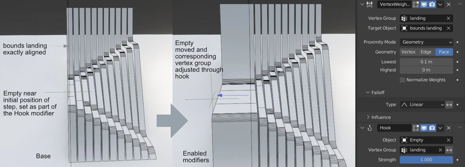
Add an empty and a hook modifier. The empty should be located near the edge of the step that will be expanded as a landing. In the hook modifier properties, set the Object to the Empty and the vertex group to Landing. Now, if the empty is moved, the object should respond. Hopefully, only the last step. However, if the whole object or a larger portion of the object is moving, then the lowest and highest limits in the proximity modifier preceding the hook modifier need to be adjusted.
If everything is working correctly, the modifiers should be positioned before the bevel modifier.
Final touches and remixes
Add a solidify modifier, with offset set to 0, and distance to 0.04m to show the depth of the steps
For rendering purposes, it may be nice to add another bevel to soften the hard edges The amount of the bevel should be really small - 1cm or 5mm. To see the effect, go to wire mode.
Now we have everything working exactly as it should. All of this is again, completely parametric. The only thing we need to edit is if we go in here and let's say, we wanna make this a bit wider, we can do that.

And if we flip it upside down, it could start to become some kind of massing. That's what's nice about these kinds of, parametric elements is that we can have a multiple number of options. Thanks for watching. Let me know if you have any comments or anything else that's quite parametric that you would like to see in regards to architecture and design with blender and see you next time.
